Ball Balance Machine
Ball and Plate Experiments
Here’s some info about my attempt at the famous Ball and Plate experiment using Arduino and Processing.
Here’s the Processing and Arduino code:
https://github.com/davidthomasson/BallAndPlateThis was my first attempt at Processing, so the code is messy. I tried to clean it up a bit after lots of experimentation, but you might still find things in there that aren’t actually being used anymore.
The Arduino code is ServoFermata (File > Examples > Firmata):
Here’s a pic of a later version of the rig than what is shown in the video:
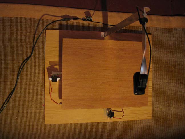
Now everything’s attached to a baseboard, so it can be easily moved.
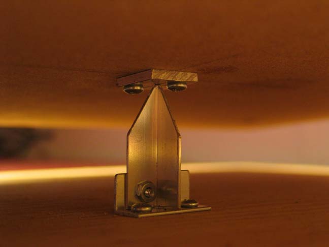
Here’s a pic of the central pivot point:
Here’s a pic of the servo-to-board connection:
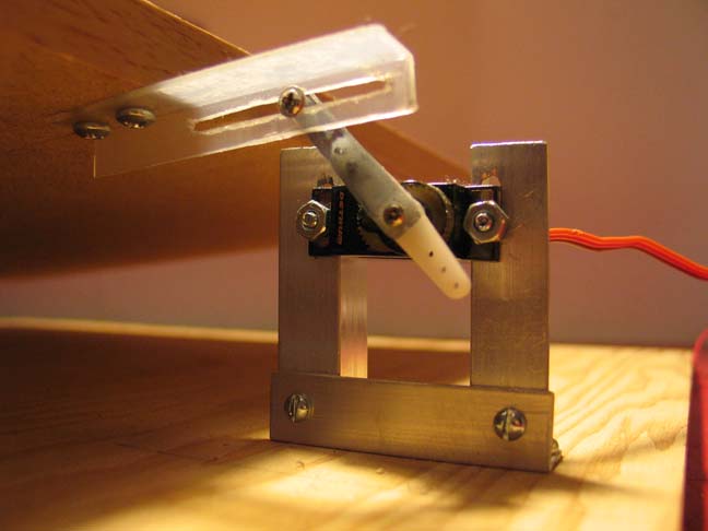
It’s important that the point of contact with the servo arm is aligned with the centrepoint of the board. The servo should be set to it’s midpoint and the height of the servo should be adjusted so that the arm is horizontal when the board is horizontal.
Any servos will do – two of the same is preferable, but not necessary since you can just set up the dimensions of each in the Processing code.
The board should be the same aspect ratio as the image from the webcam (usually 4:3). The webcam should be positioned so that it is exactly over the centre point of the board and framed so that you don’t quite see the edges of the board. This is so that not too much is seen outside the board when it is at maximum tilt which can affect the object detection. Lay some grid paper on the board to make sure that the camera is pointing straight down and all edges are parallel.
The output of the webcam should be adjusted so that there is high contrast between the board and the ball to assist with the glob tracking. I set it to black and white, but you could use a coloured ball with some adjustments to the glob settings in the code.
Here’s a typical frame of what I was working with:
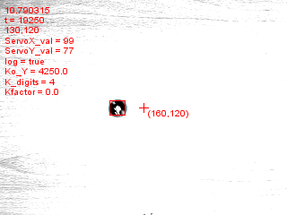
The ball needs to be as near to perfectly round as possible – I used a 1″ steel bearing bought on Ebay.
The board needs to be as flat as possible – I used a laminated MDF piece of a desk.
As far as the calculations go, I used PID control to adjust the angle of the board according to the position and velocity of the ball, as determined by glob tracking the ball in the video frame.
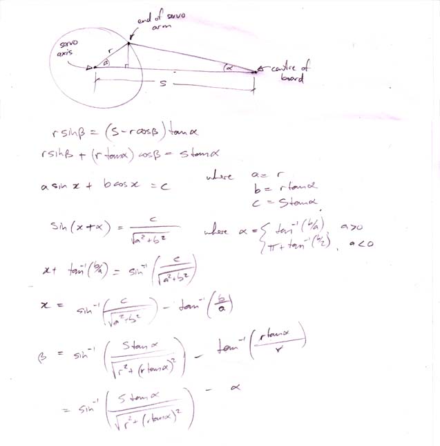
Here are the calculations I used to relate the angle of the servo to the angle of the board:
I haven’t had much experience with PID control so the tuning was just a lot of trial and error. I didn’t end up using the Integral component.
Here’s a couple of good articles on PID tuning:
http://www.ctc-control.com/customer/elearning/servotut/adjus.asp http://www.barello.net/Papers/Motion_Control/index.htmI added some code that saved various parameters to a tab-delimited text file which I then imported into Excel to analyze the movement to fine tune the control.
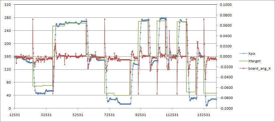
Here’s one of many plots showing expected vs actual positioning in the X dimension:
Here’s a plot of actual X-Y position vs expected:
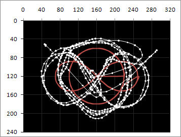
As you can see, there’s a lot of room for improvement in the tuning.
You can see in the video that the servos are always working, but it would be nice to have enough control that they are just smoothly altering position in time with the movement of the ball.
If anyone’s got any ideas on how to tune it better, I’d love to hear them.